An elevator is a complex machine used for vertical transportation within a building. It consists of two main systems: the mechanical system and the electrical control system. The mechanical system includes the traction system, cabin and door systems, balancing system, guide system, and safety protection devices. The electrical control system is responsible for power drive, logical control, and electrical safety mechanisms. This article will explore the basic components of an elevator.
Traction System
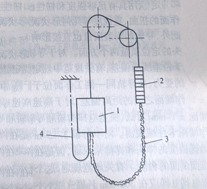
The traction system of an elevator’s function is to output power and transfer it, driving the elevator to operate. It mainly consists of a traction machine, traction steel ropes, guide wheels, and counterweight wheels, as shown in the diagram.
Traction Machine
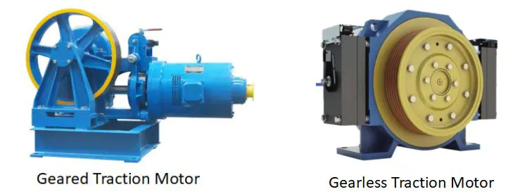
The traction machine provides the power for elevator operation. It usually consists of a motor, a traction wheel, and an electromagnetic brake. Depending on whether there is a reduction gearbox between the motor and the traction wheel, it can be divided into geared and gearless traction machines.
-
Gearless Traction Machine: The motor directly drives the traction wheel and is suitable for high-speed elevators (above 2 m/s). This elevator does not have a reduction gearbox, so it operates more efficiently with less noise and a smoother operation.
-
Geared Traction Machine: The motor drives the traction wheel via a reduction gearbox, which reduces the motor’s output speed and increases the output torque. This type is suitable for elevators with a larger load capacity.
If the traction wheel is mounted at the extended end of the main shaft, it is called a single-bearing (cantilever) traction machine. This structure is light and suitable for elevators with smaller load capacities. If the traction wheel is supported on both sides, it is called a double-bearing.
Reduction Gearbox
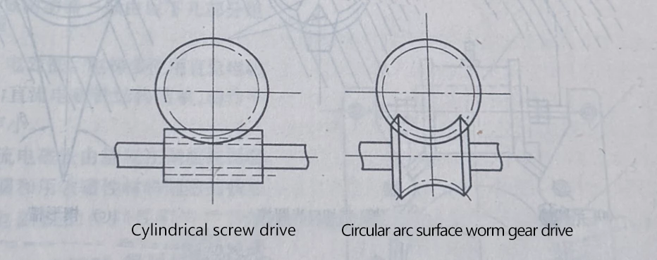
The reduction gearbox of geared traction machines typically uses worm gear and worm drive. The advantages include a large transmission ratio, smooth operation, low noise, and compact size. There are two common types of worm gear structures:
-
Worm Gear with Upper Shaft: This structure prevents foreign objects from entering the meshing surface but has poor lubrication.
-
Worm Gear with Lower Shaft: The worm is submerged in lubricating oil, providing better lubrication, but requires good sealing to prevent oil leakage.
This type of transmission design allows the traction machine to handle larger loads while reducing noise and friction.
Traction Wheel
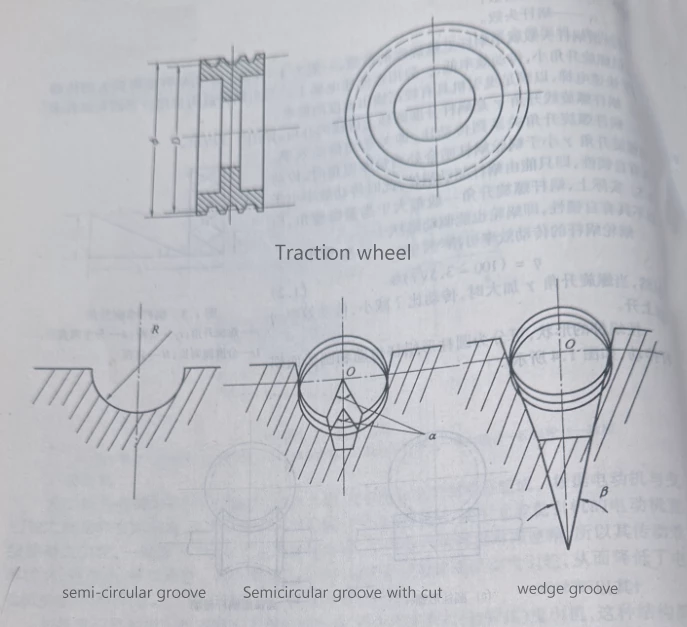
The traction wheel transfers power through the friction between the steel ropes and the grooves in the wheel, ensuring that the ropes do not slip. Common types of grooves include semi-circular, semi-circular grooves with notches, and wedge grooves. Different groove types have different friction coefficients and durability. High-speed elevators typically use semi-circular or notched semi-circular grooves to increase friction and extend service life.
Electromagnetic Brakes
Electromagnetic brakes are used to stop the elevator by generating friction when the elevator is halted. They are usually installed between the motor shaft and the worm shaft. The working principle is that when the brake lining comes into contact with the brake wheel, friction is created. The electromagnetic brake consists of several key components:
-
Electromagnet: The electromagnet usually uses a DC electromagnet because of its simple structure and low noise. The electromagnet controls the current to release or release the brake lining.
-
Brake Arm: The brake arm is used to smoothly transmit the braking force and release force, typically made of cast steel or forged steel.
-
Brake Lining: The brake lining provides the friction and is usually made from cast iron or steel plates, with a surface coated with materials that have a high friction coefficient.
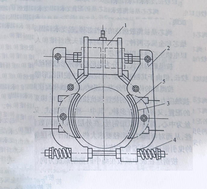
When the elevator operates, the electromagnet engages, allowing the brake to release. When the elevator stops, the electromagnet releases, and the brake lining is pressed against the brake wheel by a spring, forcing the elevator to stop.
Cabin and Door Systems
The cabin and door systems are the parts of the elevator that passengers directly interact with. They ensure the safe and smooth operation of the elevator between floors.
Cabin Structure
The cabin structure consists of the main body of the cabin and the frame. The main body includes the floor, walls, and ceiling. The frame is the supporting structure of the cabin, including beams, columns, and side beams that connect to the floor. The design of the cabin structure ensures both strength and lightness, providing high efficiency while ensuring safety.
Different types of elevators have different requirements for their cabin structure:
-
Passenger Elevators: These elevators prioritize comfort and smooth operation. The cabin frame is usually made of welded steel plates, and the floor may contain shock-absorbing rubber parts to reduce noise and vibration during operation. The cabin floor is typically covered with non-slip materials like textured plastic or carpet to ensure passenger comfort and safety.
-
Freight Elevators: Unlike passenger elevators, freight elevators are designed to carry heavier and more concentrated loads. They require stronger structures to support the weight. The cabin frame is typically made from steel beams and designed to carry heavier goods. The floor may be made of thicker steel plates, usually 4-5 mm thick. For durability, the cabin dimensions are typically deeper than wide, to accommodate larger goods, especially for vehicles or equipment transport.
-
Hospital Elevators (Bed Elevators): Specifically designed for transporting beds, stretchers, and medical staff. Their cabins are typically longer than wide to meet the needs of transporting bedridden patients. Ceiling lighting is specially designed to avoid being too bright or direct to avoid discomfort to patients. Indirect lighting is commonly used to create a softer atmosphere.
-
Observation Elevators: These elevators are mainly used in scenic buildings or tourist spots, featuring glass walls that allow passengers to enjoy the view during the ride. The cabin frame uses reinforced glass to balance strength and transparency.
-
Car Elevators: These are designed for vehicle loading and unloading. The cabins are larger, both in depth and width, to accommodate vehicles comfortably. They often feature an open-top and bottom design to make it easier for vehicles to enter and exit. The frame and floor are specially reinforced to handle the weight of vehicles, and the surface is often made of durable materials like steel or anti-slip rubber to withstand vehicle pressure.
-
Service and Dumbwaiter Elevators: These elevators are designed for carrying items such as books, food, or small appliances. Their cabins are typically made of lightweight, durable materials like stainless steel or plastic, with non-slip coatings on the floor for easy cleaning.
Weight Balancing System
The weight balancing system consists of the counterweight and compensation device, which are used to balance the weight of the cabin. The counterweight is connected to the cabin via the traction steel ropes, and it helps keep the elevator running smoothly by balancing the weight of the cabin.
Counterweight
The counterweight’s weight is usually made from a frame of channel steel and gray cast iron blocks. The load size varies between empty and rated load. The balance point of the elevator is usually formed when the combined weight of the cabin and the load equals the weight of the counterweight.
Compensation Device
The compensation device adjusts for the effects caused by changes in the length of the traction steel ropes, maintaining the elevator’s balance. It typically uses iron chains or steel ropes suspended between the cabin and the counterweight.
Guide System
The guide system consists of the guide rails, guide shoes, and guide rail frames. The guide rails determine the position of the cabin and counterweight within the shaft and provide guidance. The guide shoes contact the guide rails to help the cabin and counterweight move smoothly along the rails.
Guide Rails
Guide rails are typically made of steel with good bending resistance and are generally shaped like a T. To ensure smooth operation, the geometric error of the guide rails and the roughness of their working surfaces need to meet specific technical requirements.
Guide Shoes
Guide shoes support the cabin and counterweight through their contact with the guide rails. Common types of guide shoes include sliding guide shoes and rolling guide shoes, with the latter being used for high-speed elevators.
Guide Rail Frames
Guide rail frames fix the guide rails and bear the various forces from the guide rails. They are typically fixed to the shaft walls using expansion bolts or embedded steel plates.
Safety Protection System
The elevator’s safety protection system includes both electrical and mechanical safety devices, which ensure the elevator’s safety in the event of a malfunction.
Electrical Safety Devices
The elevator is equipped with a terminal override protection device to prevent it from going past the lower or upper station. When the elevator reaches the extreme position, the limit switch cuts off the control circuit, forcing the elevator to stop running.
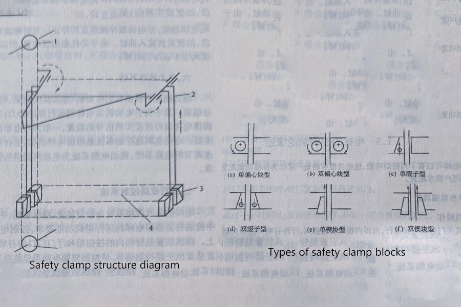
Mechanical Safety Devices
Mechanical safety devices such as speed limiters and safety clamps are used to protect the elevator’s operation when the electrical control system fails. The speed limiter can detect if the elevator is moving too fast and ensures it stops safely. The safety clamp, when the elevator moves too fast, uses mechanical force to fix the cabin in place and prevent danger.
Power Drive System
The power drive system consists of the traction motor, speed feedback devices, motor speed control system, and drive power supply system. The power drive system provides the elevator’s power and ensures the elevator operates smoothly, accelerates, decelerates, and stops accurately.
Traction Motor
The traction motor is the power source of the elevator and drives the traction system to control the cabin’s rise and fall. The motor adjusts its speed using a speed control system to suit the elevator’s various operational modes.
Speed Feedback Device
The speed feedback device provides signals about the elevator’s actual speed to the motor speed control system, ensuring the elevator is accurately controlled. Common speed feedback devices include tachogenerators and optical encoders.
Motor Speed Control System
This system adjusts the motor speed based on the elevator’s operating requirements, such as starting, braking, and leveling control, ensuring stable operation.
Drive Power Supply System
This system provides the necessary electricity to the motor, supporting the elevator’s normal operation.
Operational Logic Control System
The operational logic control system manages the elevator’s operations, ensuring that it works according to preset programs and logic. This system includes control devices, operation devices, leveling devices, and position display devices.
Control Devices
Located in the machine room, the control cabinet or control screen is responsible for controlling the elevator’s various functions based on its operational needs. It coordinates all systems to ensure the elevator operates as required.
Operation Devices
Operation devices include the button box inside the cabin and the call buttons outside at each floor. These devices are used to control the elevator’s operation, allowing users to select floors and open or close doors.
Leveling Device
This device sends leveling control signals to ensure the elevator cabin aligns accurately with the designated floor. As the cabin approaches the target floor, the leveling device adjusts the cabin’s position for precise alignment.
Position Display Device
This device displays the current floor of the elevator and shows the direction of travel using indicator lights inside the cabin and at the floor doors. It helps users know the elevator’s position and direction, making it easier to select and wait for the elevator.
For more information about the components of an elevator, please contact BDFUJI.